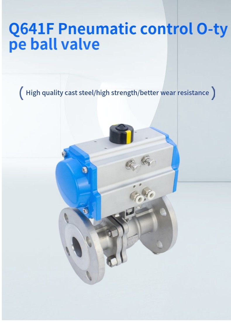
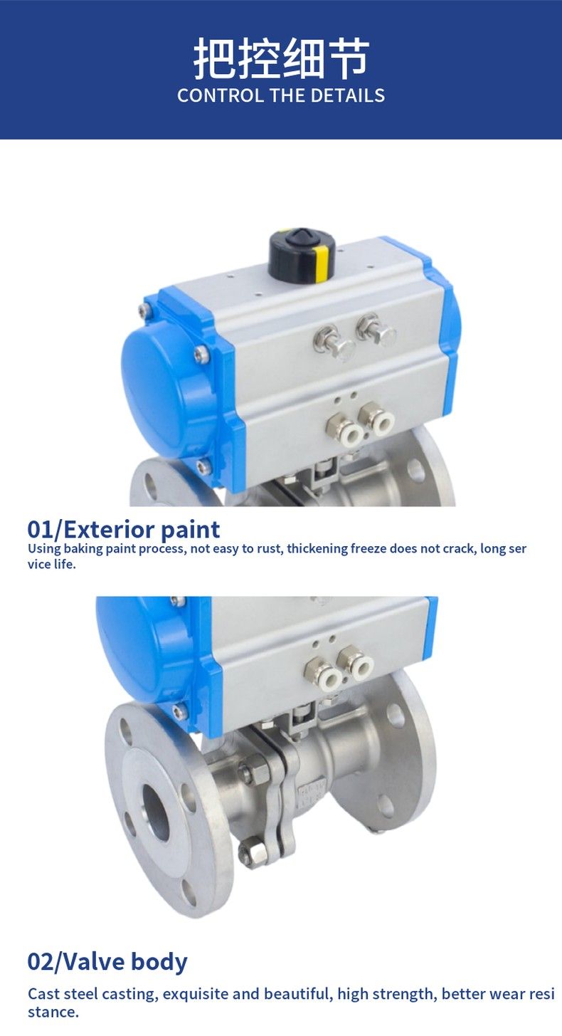
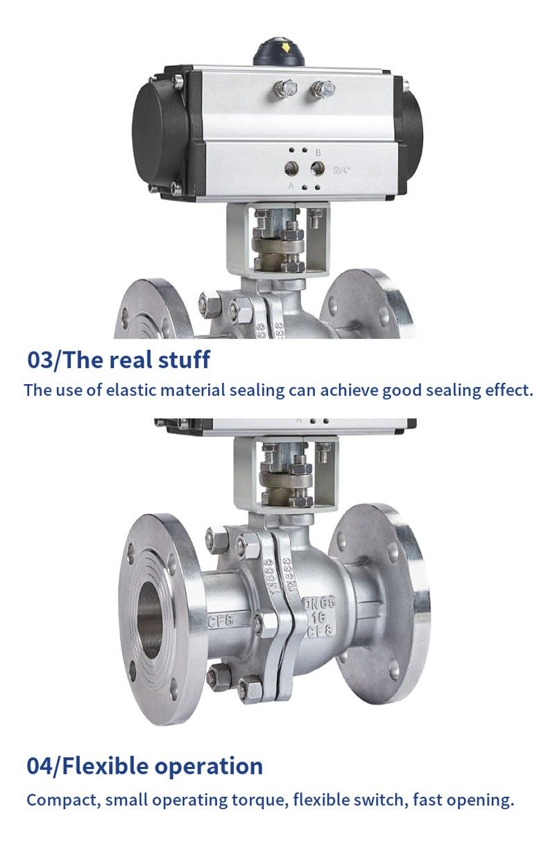
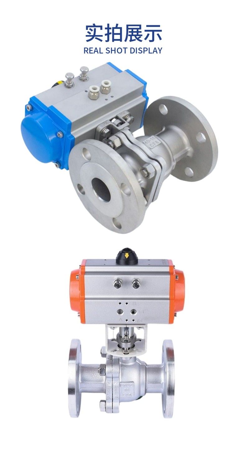
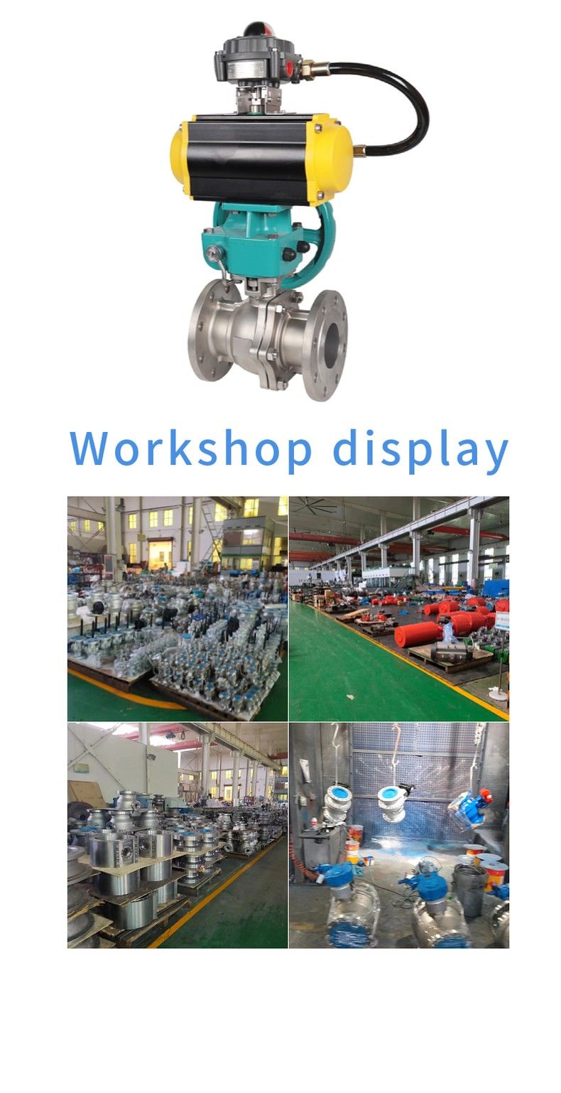
Q641F Pneumatic control O-type ball valve
Pneumatic flange ball valve
Pneumatic flange ball valve is a ball valve with a pneumatic actuator. The execution speed of the pneumatic actuator is relatively fast, and the worker does not need to do it by himself, which saves human resources and time to a large extent. Pneumatic flanged ball valve is evolved from the globe valve. It has the same rotary 90 degree lift action, the difference is that the cock body is a sphere, with circular through holes or channels through its axis. The proportion of the sphere and the channel opening should be such that when the ball is rotated 90 degrees, the sphere should be presented at the inlet and outlet, thus cutting off the flow.
Pneumatic ball valve instructions
Scope and composition
Scope: This manual applies to electric (or pneumatic) ball valves with flange connection ends.
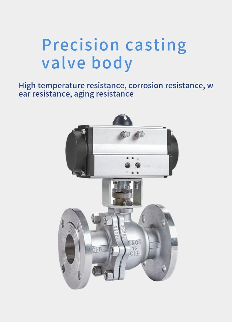
Composition: The electric (or pneumatic) actuator (20) is composed of the valve body part of the ball valve, which is connected by the bracket (18) and the connecting shaft (17).
Restrictions on use
Temperature and pressure restrictions
l The nameplate shows the maximum operating pressure allowed by the ball valve at the maximum and minimum operating temperatures.
PTFE or RTFE valve seats and seals should be used, and the operating temperature should be between -290C and 2000C. The operating temperature of other types of valve seats and seals shall be checked by KI factory.
l The nominal pressure rating (PN) of the valve, which indicates the maximum operating pressure of the valve at normal temperature. (For example: PN4.0, indicating that the maximum working pressure is 40 Bar(4.0MPa) when the operating temperature is -290C ~ 380C).
l Precautions for electric or pneumatic actuators refer to their respective instructions.
Pneumatic flange ball valve installation
1), remove the protective cover on both sides of the flange end, and wash the valve when it is fully open.
2) Before installation, the whole machine should be tested according to the specified signal (electricity or gas) (to prevent vibration from affecting the performance due to transportation), and can be installed on the line after passing the test (wiring according to the electric actuator circuit diagram).
3), before preparing to connect with the pipeline, it is necessary to wash and remove the remaining impurities in the clean pipeline (these substances may damage the seat and ball).
4) During installation, please do not use the actuator part of the valve as the lifting point to avoid damage to the actuator and accessories
5), this type of valve should be installed in the horizontal direction or vertical direction of the pipeline.
6), the pipeline near the installation point shall not be low or bear the phenomenon of external force, and the pipeline bracket or support can be used to eliminate the deviation of the pipeline.
7) After connecting with the pipeline, please use the specified torque to cross lock the flange connection bolt.
4. Operation and use
1) Before operation, it must be confirmed that the pipeline and valve have been washed.
2), the operation of the valve according to the size of the input signal of the actuator drive the valve stem to rotate: the valve is closed when the positive rotation is 1/4 turn (900). Reverse rotation 1/4 turn (900), the valve opens.
3) When the direction indicating arrow of the actuator is parallel to the pipeline, the valve is open; When the indicating arrow is perpendicular to the pipeline, the valve is closed.
Maintenance
Having a long service life and maintenance free period will rely on several factors: normal working conditions, maintaining a harmonious temperature/pressure ratio, and reasonable corrosion data
Classification and characteristics of pneumatic three-piece ball valve
Pneumatic ball valve has O-type ball valve and V-type ball valve points. O-type ball valve adopts floating structure, the ball core is precision casting, hard chrome plated on the surface, the seat adopts enhanced polytetrafluoroethylene material, the same caliber as the flow channel, great flow capacity, minimal flow resistance, no leakage when closed, generally used as a switch valve, especially suitable for high viscosity, containing fiber, granular media; V-type ball valve adopts fixed structure, the ball core is opened with V-shaped incision, which can realize proportional adjustment, and the flow characteristic is approximately equal to the percentage.
According to different process equipment can choose pneumatic or electric actuator, respectively composed of pneumatic ball valve and electric ball valve, which pneumatic ball valve if to achieve proportional adjustment must be equipped with valve positioner, electric ball valve if to achieve proportional adjustment must choose electronic electric actuator or with servo amplifier and so on.
From the material, can be divided into: carbon steel ball valve, stainless steel 304 ball valve,316 ball valve and copper ball valve
In the application, it can be divided into: high pressure ball valve and low pressure ball valve
High pressure pneumatic ball valve: mainly used in oil, natural gas, hydraulic oil, construction machinery and other industries
Low pressure pneumatic ball valve: mainly used in the medium for water and other non-corrosive pipe road!
